
| Combination of Basic Shapes |
[The purpose of this section]
Learn how to combine the basic shapes you have drawn with StarSuite Draw.
Learn how to combine the basic shapes you have drawn with StarSuite Draw.
In Draw, each (basic) shape is an independent "object". So you can freely change the location and various attributes of the shapes after they are drawn. In Draw, which has this feature, you have to create the target image by combining multiple basic shapes.
(Note)
In Paint, once you have drawn the images, the only difference between different images is the area even if they are semantically different objects. For example, assume you are drawing a dog and a cat. One portion of the screen has the colored shape of a dog and the other portion of the screen has the colored shape of a cat. Neither of them is a specific dog or cat object. Therefore, when you want to distinguish them as an "object" or a "group" and change their locations and how they overlap each other, you have to draw each of them in a different layer.
In Draw on the other hand, since each shape is an independent "object", you do not need to draw them in different layers.
Switching the Order of Multiple Overlapping Positions
To change the order of the overlapping position of an object, follow the instructions below:
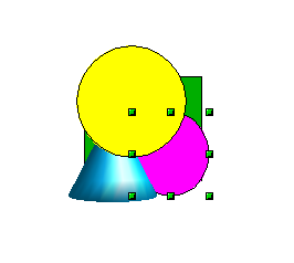
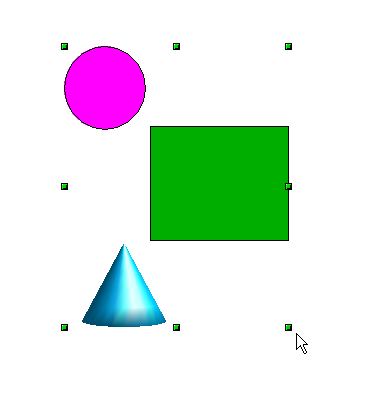
- Click on or draw a box in the shapes that you want to change the overlapping order.
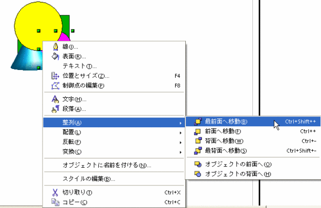
In the image below, we are trying to move the purple circle to the front (top). - Right click and in the menu displayed, select [Arrange] -> [Move to foreground].
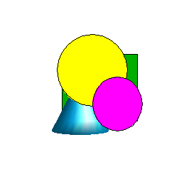
- By doing this, the shape will be moved to the foreground.
Align the Objects
To align the sides and the centers of objects, follow the procedure below:
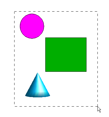
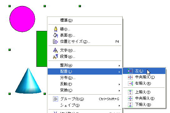
- Draw a box around all the objects that you want to align or click on them while pressing the [Shift] Key.
In the image below, we are trying to align the left edges of three shapes. - Right click and in the menu displayed, select [Arrange] -> [Left].
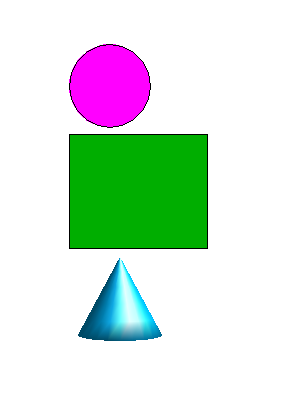
- By doing this, the edges of the three shapes will be aligned correctly.

Grouping
Combining multiple shapes into one object is called "Grouping". The shapes that are grouped become a single drawing (object) and it will be easier to move and copy complicated shapes once you group them. Of course, you can switch some parts and edit the grouped objects since there is a function called “Ungroup” to restore the grouped objects to their individual state.
Here is how to perform "Grouping" and "Ungrouping":
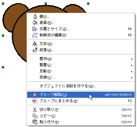
To disassemble parts that you have grouped together, select and right click on the image. From the image displayed, select [Ungroup].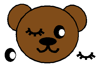
Here is how to perform "Grouping" and "Ungrouping":
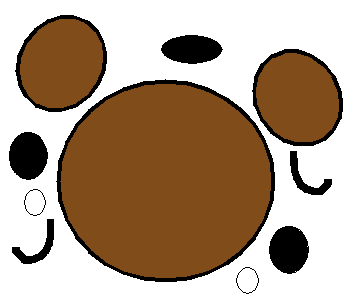
- Create shapes (parts) that you want to combine together.
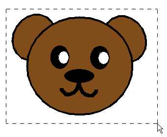
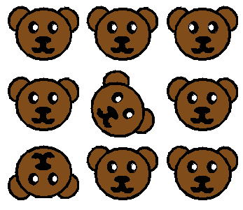
In the following example, we are going to make the face of a bear and group the parts together. - Move each part to an appropriate location to create the face of a bear, and select the entire image.
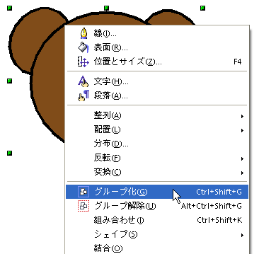
- Right click and in the menu displayed, select [Group].
- The appearance will not change, but you now have one image (a bear’s face) combining the individual parts together in a group. You can see this by selecting and moving it.
- Since it is a single image now, you can create an image such as that below by shrinking and copying it and then pasting it many times.
In the image below, some of the bear faces are further rotated or flipped.
To disassemble parts that you have grouped together, select and right click on the image. From the image displayed, select [Ungroup].
Connecting Shapes (Parts)
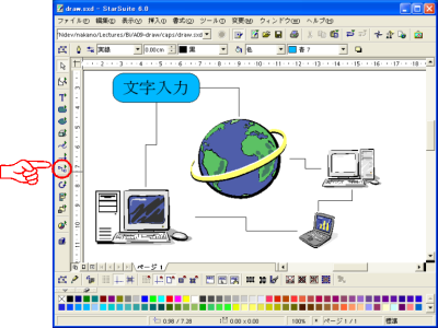
You can connect shapes (parts) using connector lines. This function is very useful because connector lines will stretch and contact properly even if you move these parts and change their position on the page. To connect parts with a connector line, click to select the Connector icon in the standard toolbar.
* Please note that in StarSuite 8, the placement of the item has changed from that of the figure below.
Once the parts are connected with connector lines, the connection will be kept even if you move a part as in the image below.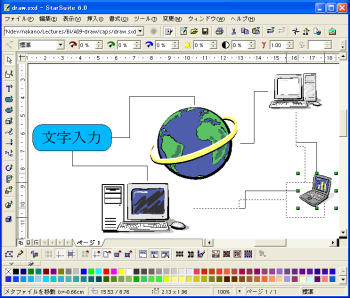
Once the parts are connected with connector lines, the connection will be kept even if you move a part as in the image below.
[Practice 9]
Add different effects to the image you have drawn in ex2.sxd using the function described in this section. When you have finished the drawing, save the file as "ex3.sxd" in the [week04] folder.
Add different effects to the image you have drawn in ex2.sxd using the function described in this section. When you have finished the drawing, save the file as "ex3.sxd" in the [week04] folder.